Applied Studies 240: Introduction to Structures
Part IV: Other Structural Elements and Reflecting on What You Have Learned
Project 10: Designing Columns, Frames, and Load-Bearing Walls
Learning Plan
- Review the Learning Outcomes.
- Read the Introduction.
- Complete the Required Reading and explore the online resources.
- Answer the Focus Questions.
- Add materials as appropriate to your Personal Archive.
- Complete Project 10. (Revisit the marking matrix.)
- Submit Project 10 as part of Collection 4 when you have completed Projects 10 and 11.
Learning Outcomes
After successfully completing this project, you will acquire proficiency in the following areas:
- Understanding of the concept of rigid frames;
- Understanding of the use of portal frames and hinge joints;
- Understanding and appreciation of the architectural and historical expressions of columns;
- Ability to analyze, compare, and explain the behaviour of different types of columns;
- Ability to apply the idea of column restraints to address buckling and deflection;
- Ability to synthesize vertical elements such as columns and load-bearing walls into stable building frames;
- Ability to design load-bearing walls as structural supports; and
- Ability to integrate your learning with your design studios to create optimum forms for columns.
Introduction
In this project, you will explore the properties of columns, frames, and load-bearing walls and then apply your understanding to a structure of your own design.
Required Reading
- Chapter 19: Designing Columns, Frames, and Load-Bearing Walls in Form and Forces: Designing Efficient, Expressive Structures
Supplemental Reading
If you found this project of interest, you may want to read the following:
- American Institute of Steel Construction. Steel Construction Manual. Chicago: AISC. Updated frequently. (See also www.aisc.org)
- Allen, E., & Iano, J. (2017). The Architect’s Studio Companion: Rules of Thumb for Preliminary Design (6th ed.). New Jersey: Wiley.
- American Wood Council. (2004). Wood Structure Design Data. Washington, DC: American Wood Council. (Also available as PDF files from awcpubs@afandpa.org)
- Concrete Reinforcing Steel Institute. CRSI Handbook. Schaumburg, IL: CRSI. Updated frequently.
- National Concrete Masonry Association. (2000). TR-121 Concrete Masonry Design Tables. Herndon, VA: NCMA.
- Association of Professional Engineers and Geoscientists of British Columbia. (2009, Revised 2015). APEGBC Technical and Practice Bulletin: Structural, Fire Protection and Building Envelope Professional Engineering Services for 5- and 6-Storey Wood Frame Residential Building Projects (Mid-Rise Buildings). Burnaby: EGBC.
- Professional Engineers and Geoscientists of Newfoundland and Labrador. (2011). Guidelines for Structural Engineering Services, April 2011. St. John’s: PEGNL.
Focus Questions
- What two different loading forces can a column experience? Explain the difference between the two.
- What two main forms of failure would a column experience? Explain the main reasons for these failures and what could be done to prevent them from happening.
- Explain the difference between fixed and hinged columns.
- What is the name of the wall and roof deck supports used in steel buildings to prevent horizontal wind loads?
- What two loads does a typical roof rafter experience? What is the method for determining the structural sizing required?
Evaluation
Your work will be evaluated using the marking matrix outlined in the Evaluation and Grading section of the Course Orientation.
Project Description
In this series of projects, you will design and analyze a variety of structural elements. Your work here will consist of three small projects:
- Column design, sizing, and architectural expression (Question 3, page 516 of Form and Forces: Designing Efficient, Expressive Structures)
- Providing a design for your project’s columns, frames, and any load-bearing walls based on two different material types of your choice
- Testing the idea of moment of inertia
Project 10a: Size a Beam with Different Materials to Carry a Load
In Chapter 19, you learned about the different shapes of columns, frames, and load-bearing walls and how the material affects their performance. From Form and Forces: Designing Efficient, Expressive Structures, complete Exercise 1 and Worksheet 19A.
Project 10b: Design Columns, Frames, and Load-Bearing Walls for Your Structure
Using the design you identified earlier (see Identifying a Suitable Project), develop a suitable design of columns and frames to support its roof structure. Use what you have learned from Chapter 19 to calculate sizes of columns, frames, and load-bearing walls of your structure. For this project, you are requested to draw a column layout and structural frame (find the required sizes of the members of the frame) using two different materials (concrete, steel, or wood).
Project 10c: Testing the Idea of Moment of Inertia: The Power of a Cross-Section
In Project 3c, you learned about the power of triangles. In this project, you will see that the way material is distributed in a structural element can have an even more profound effect on the amount it can support.
For this project, you will need the following items:
- 1 8 ½″ × 11″ sheet of ordinary paper
- tape
- dinner plates (or item you can stack as weights)
You typically would not think a piece of paper had much structural strength, but effectively distributed, it can support many, many times its own weight.
Take an ordinary sheet of letter-sized paper and fold it twice lengthwise so it looks like the paper in Figure 10.1. Record its weight.
TIP: To figure out how much a single piece of paper weighs, you can take a ream of 500 sheets, weigh them with a bathroom scale, and divide the amount by 500.
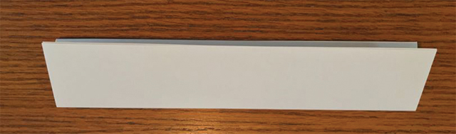
Figure 10.1. Fold a sheet of paper lengthwise in half and then in half again.
Now wrap the two ends of the paper around and insert one end into the other. Tape them together as shown in Figure 10.2.
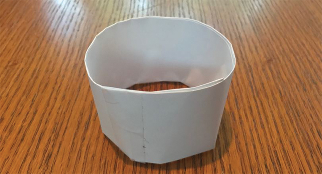
Figure 10.2. Wrap the two ends of the paper into a cylinder. Insert one end into the other and then tape them together.
See if your cylinder will hold a dinner plate (or another kind of weight). Keep loading the cylinder. Be prepared that it can hold a lot of weight (see below) and be careful when it fails. Take pictures as you are loading.
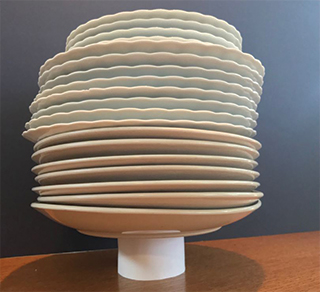
Figure 10.3. This single piece of paper supported 25 lb of plates!
Take a picture of your cylinder when it finally fails. Watch how it fails and take a picture of the effect on the cylinder. It should look similar to Figure 10.4.
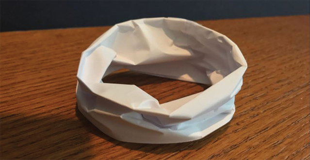
Figure 10.4. The cylinder after collapse.
How much weight did it support before failure? How does the cylinder fail? What kind of force caused the failure? How is it different from the way your triangles failed?
In this instance, the cylinder had a total weight of only 5 g and was able to support 11.3 kg of plates before failure. This means that this structure was able to support 2273 times its own weight!
It is critical as an architect that you understand why this is. Check out this blog for a simple explanation of why this is so.
The point of this exercise is to understand the power of the moment of inertia. Whether a structural component has a rectangular, circular, or tube-shaped cross-section can make a huge difference to how much it can support.
Review Terms
You should be familiar with and able to define the following terms and concepts:
bearing wall
buckling
column tie
combined member
eccentrically loaded column
effective length
girt
haunch
k, effective length factor
load-bearing wall
radius of gyration (r)
rigid frame
sag rod
short, intermediate and long
slenderness ratio
strong axis/weak axis
tube structure
Equations
sizing combined members
column buckling
radius of gyration
Submission Requirements
For Collection 4, include the following items from Project 10:
- Project 10a – Exercise 1 from Chapter 19 of Form and Forces and Worksheet 19A
- Project 10b – design of a structural columns/frame system for your own design project
- Project 10c – images and findings
Note: Do not submit Collection 4 until you have completed the requirements for Projects 10 and 11.