Applied Studies 240: Introduction to Structures
Part III: Beams
Project 7: Bending Action on Beams
Learning Plan
- Review the Learning Outcomes.
- Read the Introduction.
- Complete the Required Reading and explore the online resources.
- Answer the Focus Questions.
- Add materials as appropriate to your Personal Archive.
- Complete Project 7. (Revisit the marking matrix.)
- Submit Project 7 as part of Collection 3 when you have completed Projects 7, 8, and 9.
Learning Outcomes
After successfully completing this project, you will acquire proficiency in the following areas:
- Ability to analyze, quantify, and simplify external loading on structures;
- Understanding of bending moments and vertical loads;
- Understanding of shear and moment diagrams and their relationship to force polygons and funicular polygons;
- Ability to apply graphical and semigraphical analysis methods;
- Ability to use the equilibrium method to create shear and moment diagrams for each of the six major beam classifications;
- Ability to use shear and moment diagrams and algebraic calculations in order to calculate shear and moment forces for each of the six major beam classifications; and
- Ability to identify the maximum shear and moment forces for beam design.
Introduction
In this project, you will explore how beams bend under force. In particular, you will learn to quantify vertical force (V) and bending moment (M) and draw V & M diagrams that are a critical part of your understanding of structures.
Required Reading
- Chapter 16: Bending Actions on Beams in Form and Forces: Designing Efficient, Expressive Structures
Supplemental Reading
If you found this project of interest, you may want to read the following:
- American Institute of Steel Construction. Steel Construction Manual. Chicago: AISC. Updated frequently. This comprehensive volume gives full dimensional and structural data on every kind of steel shape in every conceivable use.
- Goldstein, Eliot W. (1998). Timber Construction for Architects and Builders. New York: McGraw-Hill Professional. An architect renowned for his heavy timber buildings gives data and advice on every aspect of the subject.
Focus Questions
- What are bending moments and vertical forces on beams?
- What are the factors that impact the bending action on beams?
- What are V & M diagrams and how are they used to find maximum intensity of bending action?
- How will these quantities help you find required sizes for beams?
Evaluation
Your work will be evaluated using the marking matrix outlined in the Evaluation and Grading section of the Course Orientation.
Project Description
In this series of projects, you will synthesize the understanding of bending action on beams with the following four projects:
- Drawing V & M diagrams and finding maximum values using Worksheets 16A and 16B
- Experimenting and comparing bending action on beams
- Analyzing the bending action of a beam with different support types
- Drawing shear and bending moment diagrams for your own structure
Project 7a: V & M Diagrams, Maximum Values (Graphical or Semigraphical)
In Chapter 15, you read about the bending actions on beams. In fact, the bending of the beam depends on factors such as the magnitude of the load, the span of the beam, and the way in which the beam is supported. V & M diagrams enable us to predict the maximum intensity of bending action that will be exerted upon any beam, taking into account the magnitude of the load, the distribution pattern of the load, the span of the beam, and the way in which the beam is supported.
There are eight general loading patterns you should know. To learn more about shear and moment diagrams, refer to the OER entitled “Common Vertical Force and Bending Moment Diagrams” to help you better understand this topic.
Practise drawing V & M diagrams and finding maximum values of these variables for different beams and conditions. Complete Exercise 1 at the end of Chapter 16 in Form and Forces: Designing Efficient, Expressive Structures using Worksheets 16A and 16B.
Project 7b: Understanding the bending action on beams
You have now studied the bending action on beams and learned how to draw the V & M diagrams, as well as how to find the maximum value of these. In the next project, you are going to put these into action in a home experiment.
For this project, you will need the following items:
- rectangular-section pasta such as linguine or fettuccini (spaghetti will also work)
- tape
- string
- 2 small rubber bands
- paper clips or metal wire
- paper cups
- coins or marbles (or anything that can be used as weights)
- 2 stands of equal height (e.g., boxes, books, chairs)
Materials can be replaced with other items you have at home. The experiment should look something like Figure 7.1.
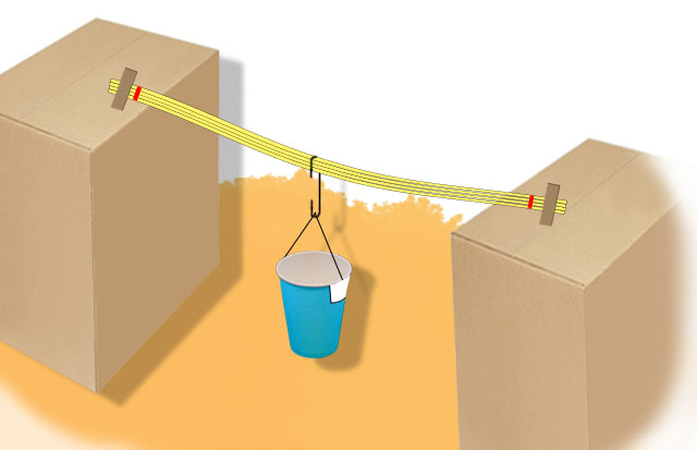
Figure 7.1. An image of how your pasta beam and load might look.
First, attach a few strands of pasta together with rubber bands at both ends. If you have rectangular pasta, like linguine or fettuccini, stack them neatly on top of each other to make a rectangular section beam.
Attach a string to the edge of the paper cup with tape (so you can hang it like a bucket).
Rest your pasta beam onto the two stands of equal height. Tape the pasta beam to the stands for stability.
Add some weights into the paper cup.
Using the paper clip as a hook, hang your paper cup onto the beam.
TIP: To improve this experiment, draw intervals (at every 1cm, for example) on the pasta beams to be able to visualize the span length and placement of your loads.
Now you can simulate different conditions of loading by moving your weight in different positions on your pasta beam. Try adding more weights and note the difference in bending. If you add more cups, you can also try adding multiple loads.

Figure 7.2. Your pasta beam and load should look something like this.
- Simulate at least three different “bending action on beam” conditions by changing either the magnitude of the load (adding more weights), the distribution pattern of the load (adding more weights or more hooks), the span of the beam (changing the position of the beam on the stands), and the way in which the beam is supported (removing one stand would simulate a cantilever, for example).
- Take a photo of each condition you experiment with.
- With every beam condition you produce, draw the V & M diagram and compare it with what you see. Note your observations and comment on whether the V & M diagrams you drew accurately predict the bending of the beams.
- Submit the photos of your experiment, your V & M diagrams, and your observation analysis along with your collection.
TIP: If you are using a rectangular pasta (e.g., linguine or fettuccini), try rotating the beam from a horizontal section to a vertical section and observe whether there is a difference in the bending action.

Project 7c: Analysis of the Bending Action of a Beam with Different Support Types
For this project, you are going to analyze bending in a beam with different support types. Observe how the beam is supported and connected. Try to imagine how this would affect the bending of the beam. Also, observe how the beam is loaded, what will happen in V & M, and what conclusions you can draw.
Again, you may want to refer to the OER entitled “Common Shear and Moment Diagrams” to help you better understand this topic.
Complete Exercise 2 at the end of Chapter 16 in Form and Forces: Designing Efficient, Expressive Structures. Develop an answer to the components mentioned for this exercise and present your response as part of the collection.
Project 7d: Drawing Shear (V) and Bending Moment (M) Diagrams for Your Structure
Using the design you identified earlier (see Identifying a Suitable Project) and referring again to the OER entitled “Common Shear and Moment Diagrams,” choose a beam from a selected part of the structure of your building. The beam could be part of a floor or roof structure. Identify the connections and loads that are carried by the beam and draw the shear and bending moment diagrams for your beam. You will need to consider the following:
- the live and dead loads you identified in Project 1e
- the framing system you developed in Project 6b
Review Terms
You should be familiar with and able to define the following terms and concepts:
bending moment (M)
bending moment diagram
cantilever
concentrated load (P)
continuity of beams
degrees of curves
zero
first
second
third
distributed load
distributed load per unit of span length (w)
eccentricity
encastered beam
indeterminate
longitudinal and transverse forces
moment diagram
overhanging ends
point of inflection
pressure line
semigraphical method
shear
shear diagram
superposition
third points
vertical force (V)
vertical force diagram
Submission Requirements
For Collection 3, include the following items from Project 7:
- Project 7a – Worksheets 16A and 16B
- Project 7b – images and findings
- Project 7c – analysis for the beam with different support types
- Project 7d – V & M diagrams for your own design project
Note: Do not submit Collection 3 until you have completed the requirements for Projects 7, 8, and 9.