Applied Studies 240: Introduction to Structures
Part II: The Flow of Forces
Project 3: Designing Efficient Trusses
Learning Plan
- Review the Learning Outcomes.
- Read the Introduction.
- Complete the Required Readings and explore the online resources.
- Answer the Focus Questions.
- Add materials as appropriate to your Personal Archive.
- Complete Project 3. (Revisit the marking matrix.)
- Submit Project 3 as part of Collection 2 when you have completed Projects 3, 4, 5, and 6.
Learning Outcomes
After successfully completing this project, you will acquire proficiency in the following areas:
- Understanding of the correct utilization of simple trusses in domestic and commercial scale structures;
- Ability to identify common truss types and their uses;
- Ability to apply the method of sections to analyze simple trusses;
- Ability to apply the method of members to determine the support reaction of three-hinged arches;
- Ability to apply the method of joints to design simple trusses; and
- Ability to design space frames using rigid links and ball and socket joints.
Introduction
In this project, you will look at the structural power of triangles and show how that power can be combined into various kinds of trusses, which is an essential structural form in contemporary architecture.
Required Reading
- Chapter 6: Designing with Multipanel Trusses in Form and Forces: Designing Efficient, Expressive Structures
- Chapter 10: Designing Efficient Trusses in Form and Forces: Designing Efficient, Expressive Structures
Focus Questions
- If triangles are such efficient structures, why aren’t they always used?
- If the cube is a rigid three-dimensional structure, then why is it so unstable when you are trying to make one?
- If you were asked to analyze the performance of a truss, which method would you choose: graphic statics, the method of joints, or the method of sections? Why?
Evaluation
Your work will be evaluated using the marking matrix outlined in the Evaluation and Grading section of the Course Orientation.
Project Description
In this series of projects, you will continue designing structures through graphic statics. Your work here will consist of three small projects:
- Understanding the power of triangles
- Completing the design of a multipanel truss using Worksheet 06A
- Completing the design of a constant-force truss using Worksheet 10B
Project 3a: The Power of Triangles
You’ve probably often heard that form follows function in architecture, but the truth of the matter is a little more complicated. In the last section, you learned that an upside down catenary provides an effective form for a funicular vault. In this project, you will explore the power of triangles.
Of all polygons, only triangles are rigid. The best way to understand this is by considering other polygons. If you make a square with four equal sides and pin connectors at each corner, it’s easy to push it into the shape of a parallelogram. The same is true for pentagons, hexagons, and other multisided shapes.
Triangles are different. The angle of each corner is constrained or held in place by the one side of the triangle that is opposite the angle. Opposite each angle, there is one side and one side only. This is not true for squares, pentagons, and other figures. So in a triangle, the only way that angle can change is if the opposite side stretches or shrinks. If your triangle is made of rigid members with hinged corners, then it will not change shape until those members break.
The other critical characteristic of triangles is that when they are loaded, each side is either completely in tension or compression.
Making a structure out of triangles is a basic approach to structures. In many ways, a truss is just a beam made out of triangles. Again, when loaded, each strut in a truss is either in tension or compression.
But that’s not the full story on rigid structures. While a triangle is the only rigid shape in two dimensions, there are numerous rigid shapes that are three dimensional. In fact, all convex polyhedral are rigid. A convex polyhedral is one in which a line connecting any two vertices is contained within the polyhedral. This includes all the regular polyhedrons such as the tetrahedron (which is made up of triangles), the cube (which is made up of squares), or the dodecahedron (which is made up of pentagons). Even many nonconvex polyhedral are rigid. These include star-shaped forms such as the stellated dodecahedron.
As you will see in this project, however, rigidity isn’t quite so cut and dry.
For this project, you will need the following:
- mini-marshmallows
- spaghetti or similar pasta
- cutting surface
- utility knife
- dinner plates
First cut six equal lengths of pasta about 9 cm long. Form a triangle with three pieces of pasta by connecting them with mini-marshmallows. Attach another piece to each marshmallow so they are sticking straight into the air; then connect the three loose ends with another marshmallow to make a tetrahedron (as shown in Figure 3.1). Your shape should have four sides, each of which is an equilateral triangle. Take a picture of this. Make two more tetrahedrons in the same fashion.
Leave them overnight. As the marshmallows dry out in the air, they form a bond with the pasta that makes them very strong. If you load them before they dry out, the structures will fail at the joints.
Weigh all the shapes if you can—although they are probably too light to register on a typical bathroom scale.
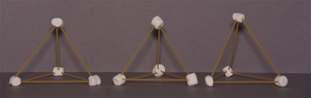
Figure 3.1. Your pasta tetrahedrons should look something like this.
Place your three tetrahedrons in a triangle and see if they can support a dinner plate. Take a picture of this. If they can support one plate, then add another and another until the structure fails. Take pictures as you go and record where the structure fails. Weigh the number of dinner plates your structure was able to successfully support. Then calculate the ratio of the weight of the structure to the weight it supported.
Watch the video to see how the structure failed. Referring to the OER “Basic Forces” document, what kind of force caused this structure to fail? Why?
In this instance, the three tetrahedrons shown in Figure 3.1 had a total weight of 13.5 g and were able to support four plates, each weighing 318 g (or 1272 g in total) before failure. This means that this structure was able to support 94 times its own weight.
Now use the same method to build a cube. Even though a cube is a convex polyhedral and, therefore, should be rigid, in practice it is not. Theory and practice are not always the same. To stabilize your cube, add diagonal bracing. These braces will need to be longer than the sides of the cube, but you can probably estimate their length by eye. See how few braces you need to add to stabilize your cube. After leaving it overnight, load it with dinner plates. Take pictures at every step and then calculate the ratio of the weight of the structure to the weight it supported.
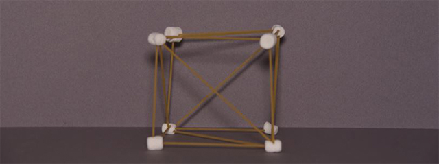
Figure 3.2. Your pasta cube should look something like this.
Watch the video to see how the structure failed. Referring to the “Basic Forces” document, what kind of force caused this structure to fail? Why?
In this instance, the cube had a total weight of 11.9 g and was able to support three plates, each weighing 318 g (954 g in total) before failure. This means that this structure was able to support 80 times its own weight.
The point of this exercise is to understand the power of triangles. Whether it’s a truss, an open web steel joist, bracing, or a space frame, triangles provide some of the most stable structures bar none.
Project 3b: Designing a Multipanel Truss
In this next project, you will begin your study of trusses. It relates to the readings in Chapter 6 of your eText. Trusses use the properties of triangles to span large distances with a minimum amount of material and, hence, weight.
Earlier, you learned about pin connections. Sometimes pin connections are also called hinges. In general, trusses use internal hinges, which are essentially pin connections but are suspended in the structure and not anchored to a surface (such as the ground) like the pins you studied earlier. These internal hinges also impact the structural determinacy of the structure, which is explained in the following video:
Dr. Structure. (2013, October 11). SA03: Analysis of beams having one or more internal hinges. [Video file].
There are a number of ways to analyze a truss. These include the following:
- graphic statics (which is what you will use in your assignment)
- method of joints (which is explained in Chapter 6 of your eText)
- method of sections
The method of joints is more often used in numerical analysis, but you should also be familiar with the method of sections. Watch the following video:
Dr. Structure. (2014, April 2). SA10: Truss Analysis: Method of Sections. [Video file].
As this video notes, if you need to analyze the entire truss, then it is best to use the method of joints; the method of sections is better for analyzing just a few of the members of the truss.
Use Worksheet 06A to complete the analysis of a multipanel truss. This is described in more detail on p. 156 of your eText. Make sure you explore the resources on the supplemental site listed on that page.
Project 3c: Designing Efficient Trusses
This project explores the design of constant-force trusses. It relates to the readings in Chapter 10 of your eText.
The idea here is to develop shapes that are very efficient in their use of material. A truss that is shaped so its top or bottom chord will experience a “constant force” across its entire length when loaded under normal circumstances is such a shape.
Constant Force Triangles
The idea of constant force is an important one. When the stress due to compression or tension is constant through the cross-section of a structure, it is called direct stress. Bending stress, on the other hand, changes across the cross-section from a maximum compressive stress to a maximum tensile stress. This explains why direct stress is a more efficient use of material than bending stress since every fibre in the material is subjected to the same stress.
A property of elements under direct stress is that they change very little in comparison to elements under bending stress. You can see this for yourself by pushing on both ends of a steel ruler. You won’t be able to see any change in its length. On the other hand, if you press one end of the ruler to your desk with your left hand and allow it to protrude (like a cantilever) into the air and press with the same amount of force with your right hand, you should see a fair amount of deflection. In fact, bending deflection can be two or three thousand times greater than compressive deformation.
This is why you want to have the elements of your structure in pure tension or compression wherever possible. This is, however, difficult to achieve (as can be seen in Figure 3.3).

Figure 3.3. Direct stresses can only develop if each joint allows for unrestrained rotation.
In Figure 3.3, the cable will be in tension (T) and the strut will be in compression (C). There will be very little displacement.

Figure 3.4. When the joints are fixed, the bottom strut will experience bending.
In this figure, all the joints are fixed and the bottom strut behaves like a cantilever beam and is subjected to bending stress.
TIP: Watch the pasta videos again. With your understanding of direct and bending stresses, can you explain more precisely why the structures failed?
Now use Worksheet 10B to complete the design of the bridge as laid out on p. 297 of your eText.
Submission Requirements
For Collection 2, include the following items from Project 3:
- Project 3a – images and findings
- Project 3b – Worksheet 06A
- Project 3c – Worksheet 10B
Note: Do not submit Collection 2 until you have completed the requirements for Projects 3, 4, 5, and 6.