Applied Studies 240: Introduction to Structures
Part I: Introduction to Graphic Statics
Project 2: Force Systems and Designing Unreinforced Masonry
Learning Plan
- Review the Learning Outcomes.
- Read the Introduction and Key Concepts.
- Complete the Required Readings and explore online resources.
- Answer the Focus Questions and the Discussion Forum Question.
- Add materials as appropriate to your Personal Archive.
- Complete Project 2. (Revisit the marking matrix.)
- Submit Project 2 as part of Collection 1 when you have completed Projects 1 and 2.
Learning Outcomes
After successfully completing this project, you will acquire proficiency in the following areas:
- Understanding of the concept of force systems (and equivalent force systems in particular);
- Ability to identify different types of force systems;
- Understanding of the ideas of moments and the equilibrium of forces;
- Ability to identify different types of connections and supports;
- Ability to apply your understanding of equivalent force systems to analyze structural systems;
- Ability to calculate beam and truss reactions, graphically analyze arches, and trace the loads in arches and vaults; and
- Ability to demonstrate these techniques to design steel frames structures and funicular masonry arches and vaults.
You will be using many of the resources described in Project 1. You may want to revisit this information.
Introduction
This project continues your exploration of graphic statics and structural analysis. In particular, it introduces moments, reactions, and connections through the design of building on a vertical site and it explores load tracing and the analysis of arches and vaults through the design of an unreinforced masonry structure.
Key Concepts
Force Systems
In this project, you will explore three different force systems:
- concurrent coplanar force systems
- nonconcurrent coplanar force systems
- parallel coplanar force systems
Coplanar means that all the forces lie in the same two-dimensional plane. In other words, all the forces can be drawn on a flat surface with none of them poking up or down into the third dimension. The x-y coordinate system introduced in Project 1 is a two-dimensional plane, so these force systems are often drawn on the x-y plane to analyze them. (Note: Noncoplanar force systems are more difficult to solve and are not part of this introductory course.)
Concurrent Coplanar Force Systems
When you designed a suspension footbridge in Project 1, you were using a concurrent coplanar force system as shown in Figure 2.1. (In all the diagrams that follow, F indicates a force vector.)

Figure 2.1. Concurrent coplanar force system.
As you can see, all the lines of action pass through the same point. If you designate that point to be (0,0) in the xy plane (as shown in the diagram), then it can often simplify your analysis. (Note that this is an arbitrary designation; for example, you could have located the point (0,0) at the end of F4.)
Structural systems often try to create a concurrent coplanar force system in three dimensions with all the lines of action intersecting at a single point. Creating concurrent coplanar force systems is a critical means of ensuring stability; you will be asked later in this project to find other examples of this kind of system.
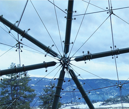
Figure 2.2. The entrance canopy of the Sparkling Hill Resort in Vernon, British Columbia, is a good example of a concurrent force system with steel tubes and cables intersecting at the same points (Architect: Cannon Design). Note these structural members are not coplanar but rather form a three-dimensional system.
Nonconcurrent Coplanar Force Systems
In Project 2, you will also be looking at nonconcurrent coplanar force systems. Such a system is shown in Figure 2.3.

Figure 2.3. Nonconcurrent coplanar force system.
You can see that while these are the same forces and lines of action as in the previous figure, they have been moved so that they do not all intersect at a single point and, as such, are nonconcurrent. They are, however, still coplanar.
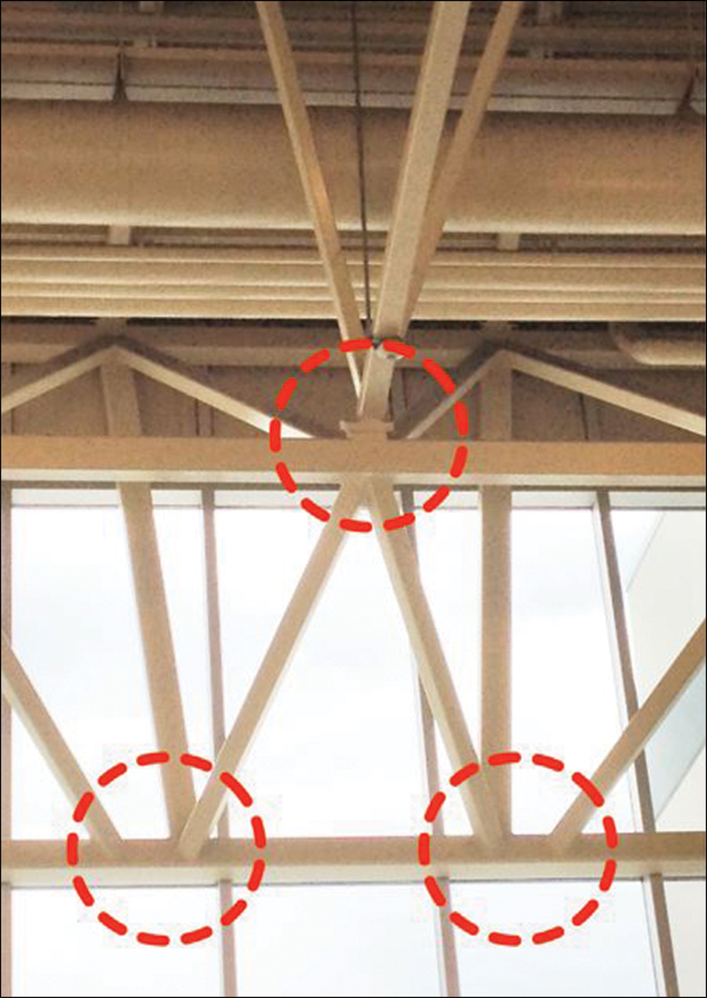
Figure 2.4. Nonconcurrent nonplanar force system.
This image shows a variety of structural members that are neither concurrent nor coplanar. This situation may have been due to reasons of cost or other factors but in general, this is not recommended.
Parallel Coplanar Force Systems
As part of one of the projects in this section, you will also be dealing with parallel coplanar force systems. In fact, because these systems apply to many situations with beams, you may find that you deal with parallel coplanar systems more than any other system. Figure 2.5 illustrates one of these systems.

Figure 2.5. Parallel coplanar force system.
As you can see, all the forces (marked F) and all the lines of action are parallel to each other. The blue arrows marked RL and RR are also forces, but they are called reactions (defined below). This is often the situation when a simple beam is subjected to a variety of gravity loads or dead loads. You will be working a lot with parallel coplanar force systems.
Reactions
As you have seen in the examples in Project 1, loads exert forces on buildings. For the building to remain stationary (or in static equilibrium), it must resist (or push back against) those forces—otherwise the building will start to move in some way and then collapse. The forces that a building exerts to counter the forces of its loads are called reactions. This follows from Newton’s Third Law that for every action (like a load), there is an equal and opposite reaction. For a building to remain in static equilibrium, there must be sufficient reactions to counter all the forces applied to it.
If you haven’t done so already, download and examine the OER entitled “Loads on Buildings.”
If there is a 500 kN dead load from the walls pushing down on the foundation, then to remain stable, there must also be a 500 kN reaction pushing upward to resist it. Similarly, if there is a live load of snow pushing down on the roof with a force of 2 kN/m², then there must be an equal but opposite force pushing upward. If there is a 20 kN lateral load caused by the wind that pushes the building to the right, then it must be resisted by a 20 kN force pushing to the left.
Each and every one of these loads and reactions, whether known or unknown, must be considered in determining the equilibrium of a structure.
Connections and Supports
These reactions occur at the supports or points of contact of the structural components that are subjected to the loads. These points of contact include the connection of a beam to a column or a column to a foundation or a roof truss to a wall.
In general, these connections create two kinds of reactions:
- A support can prevent the translation (or movement in a straight line) of a structural component by exerting a force on the component in the opposite direction of the load.
- A support can prevent the rotation (or circular movement) of a structural component by exerting a couple moment on the structural component in the opposite direction of the load. (See the next section for the definition of a moment.)
Understanding the different kinds of supports and connections is critical to understanding structures because buildings can often fail at these points of connection. Moreover, it is at these supports and connection points that the reactions occur. To aid you with this understanding, download and examine the OER entitled “Structural Connections.”
One kind of connection not listed in that table is a hinge. While hinges and pins both exert the same kinds of reaction forces, a pin is usually fixed or attached to a structure; a hinge may not be. You will be exploring the unique properties of hinges in a later section.
Moment of a Force
The moment of a force is a physical quantity that is a measure of that force’s tendency to cause an object to rotate around a specific point or axis. This is different from the tendency of an object to move (or translate) in a straight line along the line of action of a force. A moment occurs every time a force is applied that does not pass through the centroid of the object. A moment develops if a force does not have an equal and opposite force (or reaction) directly along its line of action.
When you are standing on a cantilevered balcony, the live load of your body weight pressing down on the concrete of the balcony causes a moment to develop at the point where the cantilevered balcony joins the wall.
Moment about an Axis
You use the concept of a moment every time you use a wrench to loosen or tighten a nut. You apply a force at the end of the wrench and the moment of the force causes the nut to rotate around an axis at the other end of the wrench. The moment of a force is also called torque.
Moments are also represented by vectors, but in the two-dimensional world of an x-y plane, the moment vector (like its axis of rotation) is usually perpendicular to (or sticking straight out of) that plane, so it appears as just a point at the position of the axis of rotation.

Figure 2.6. Moments of a force.
These diagrams show both a top view (which is how it’s usually shown), on the right, and a three-dimensional side view, on the left, of the same moment of a force working around an axis (in this case, the Z axis). The perpendicular distance from the force to the axis is labelled “d” and is critical in calculating the value of the moment.
If you are having trouble understanding this topic, watch the following video about moment of a force:
Wang, Y. (2013, February 1). What is moment of a force? [Video file].
Moment of a Couple
A couple is created when two equal forces act in opposite directions on an object but not through the same point. In other words, they are equal in magnitude, opposite in sense or direction, and do NOT share the same line of action. This creates a turning effect or a rotation. A good example is when you use both hands to turn the steering wheel of a car.
The moment of a couple is calculated by multiplying the magnitude of one of the forces times the perpendicular distance between the two forces.
In this diagram, two equal forces of 300 kN are acting in opposite directions about Point A. The distance between the forces is 10 m. This produces a moment of 300 kN times 10 m that equals 3000 kNm.

Figure 2.7. Moment of a couple.
If you are having trouble understanding this topic, watch the following video about the moment of a couple:
Wang, Y. (2013, February 8). Statics lecture 15: Moment of a couple. [Video file].
As you will see, the moment of a couple is a very useful tool in solving structural problems. Here’s why: This kind of force couple creates a pure moment. It is called a pure moment because its effect is to cause a rotation (or circular motion) but not a translation (or a straight line movement). This means it is a free vector (see definition below) and a free vector has the critical property that its effects are independent of its point of application. As such, free vectors (such as the moment of a couple) can be moved around the plane. In structural analysis, this allows you to move a force around to a place that will simplify your calculations. See below for some applications.
The Moment of a Couple Is a Free Vector
A free vector is a vector that does not have a specific line of action. Its direction and magnitude must remain the same, but its point of origin can be moved around the plane.
Analyzing Structures
You may also want to download the OER entitled “Solving Simple Structural Problems.”
Drawing a Free-Body Diagram
Building a free-body diagram (FBD) is an important first step.
Example 1: Cantilever Beam
Start with a cantilever beam 6 m in length with an applied load of 2000 N as shown below. The weight of the beam is 200 kg.

Figure 2.8. Cantilever beam with load.
First draw the FBD. Here you can see that this is a parallel coplanar force system. Also note that the FBD is drawn as if it were in an x-y coordinate system with x as the horizontal dimension and y as the vertical one.

Figure 2.9. Free-body diagram of Figure 2.6.
One important thing to remember is the difference between weight and mass and how that is translated into force. In this example, you are told that the mass of the beam itself is 200 kg.
In Project 1, you were introduced to the difference between weight and mass. Basically, weight is a force that is determined by mass and gravity. Remember that the terms weight and mass are often used interchangeably (and incorrectly). You may often get a structural problem that says “the weight of a beam is 200 kg,” but what is meant is the mass of the beam is 200 kg. This is an important thing to remember since it will affect many of your structural problems.
If you are given the mass of a structural component, then you must convert it to its weight in order to understand the force that mass is exerting. On Earth, the reason why a mass exerts a force is because of gravity. So you can calculate the weight of an object by multiplying its mass times the acceleration due to gravity. On Earth, this is 9.81 m/s². In the metric system, m/s² is the way acceleration is measured or how the velocity of something changes with time. In this case, it means that every second an object is free falling, its speed increases by 9.81 metres per second.
This means that to convert a mass of 200 kg to its weight, you must multiply it by 9.81 m/s². So in this case, the force due to gravity (or the weight of the beam) is 200 × 9.81 or 1962 N as shown in Figure 2.9.
Note: When you are using this formula, always make sure the mass is in kilograms.
It will also make things simpler if you create a reference point to analyze the reactions at the supports. In this case, choose the point of contact between the beam and the wall as the reference point or “A.” Then measure the distance from the reference point to the lines of action of the forces acting on the beam.
Because the cantilever is joined to the wall with a fixed connection, you know there will be three reactions at A as shown:
- A horizontal reaction called Ax that resists movement of the beam in the x direction
- A vertical reaction called Ay that resists movement of the beam in the y direction
- A moment called Ma that resists rotation of the beam
(See the “Connectors” OER for more on this.)
To make things even simpler, we say that the weight of the beam due to gravity acts at the beam’s centre of gravity or at the centroid of the beam (in this case, 3 m from the wall).
As noted earlier, a moment is equal to the product of the distance between the reference point and the line of action of a force times the magnitude of that force. (Review the definition of a moment if you are unclear about concepts such as the axis.)
Components and Resultants
The point is to use what you have learned to solve structural problems, so first and foremost, remember that all these force systems of actions and reactions, including the tendency to overturn, or moments, can be described using the x and y coordinates.
To do this, the forces may need to be broken down into their x and y components or you may need to combine a number of forces into a single resultant force. Choose one approach or the other based on the information you are given in a particular problem. The next few examples apply these ideas to actual problems.
Example 2: Cantilever Beam with Two Loads
The first situation will involve finding the resultant of two forces.

Figure 2.10. Cantilever beam with two loads, Example 2.
As you can see, there are two vertical forces (red arrows) acting in opposite directions (one up, one down). You want to find the resultant that is equal to the combination of these two forces. It is an arbitrary decision, but in the x-y coordinate plane, a positive value usually represents an upward force, and a negative value is a downward one. In this instance, you have a positive force of 30 kN acting upward on the beam and a negative force of 50 kN acting downward or −50 kN.
Adding these two forces together, you get the magnitude of the total force acting on the beam, which equals 30 kN + (−50 kN) or −20 kN. Call this force R.
Next, calculate where this force will act on the beam if it is to be equivalent to the original loading. As shown in the diagram, use x to designate the distance of the resultant force from the end of the cantilever.

Figure 2.11. The resultant force, Example 2.
To find the value of x, analyze the moments of the original forces. In this case, analyze the moments about the point of reference shown in the diagram as A. Designate (arbitrarily) that a clockwise rotation will be positive and a counterclockwise rotation will be negative.
As noted previously, you calculate a moment by multiplying the magnitude of the force times its distance from the point of reference. Since there are two forces at work here, there will be two moments. One will be created by the −50 kN force and the second by the 30 kN force.
The −50 kN force is 5 m from the point of reference, so it generates a moment of −50 × 5 or −250 kN-m.
The 30 kN force is 8 m from the point of reference, so it generates a moment of 30 × 8 or 240 kN-m.
(As noted above, the 50 kN force is acting in the opposite direction to the 30 kN, so it is a negative.)
This can be summarized as follows:
This means that the sum of the moments about the point of reference A is 10 kN-m. Now you know that the resultant of the two original forces has a value of −20 kN and it must also generate a moment of −10 kN-m at the point of reference. This can be written as follows:
Substitution gives you the following:
This means that x equals 9.5 m and you can say the resultant force is located 9.5 m from the end of the beam or .5 m from the point of reference.
Equivalent Force Systems
Sometimes, in order to analyze a structural component, an equivalent force system is created that has exactly the same effect as the initial force system but which simplifies the calculations. Equivalent force systems are one of the most powerful tools we have for analyzing simple structures.
Creating Equivalent Force Systems with Moment Couples
As you learned earlier through the principle of transmissibility, forces can act at any point along their lines of action. This means you can move the force along the line of action to a point that may simplify your analysis.
Often, however, the point you want to analyze is not on the line of action of a particular force. In these situations, you can create an equivalent force system by moving the force to the point and adding a moment couple to the component.
In these instances, neither the magnitude nor the direction of the force vector is changed. Instead, you move the force to the desired point and then take the moment of the force about that point which creates a moment couple. In fact, because moment couples are free vectors (as defined previously), they can be placed anywhere on the FBD.

Figure 2.12. A variety of forces can be simplified into a single force and a moment couple.
This can make your analysis much easier. In fact, this seems almost magical—no matter how many forces are acting on a structure, they can all be replaced by a single force and a moment couple acting on a single point of your choosing. Both force systems are statically equivalent.
Here are the steps to do this:
- First, choose a point to take the equivalent force couple system about. Any point will work, but the point you choose will affect the final values you find for the equivalent force couple system. Traditionally, this point will either be the centre of mass of the body or some connection point for the body.
- Next resolve all the forces not acting through that point to a force and a couple acting at the point you chose.
- To find the “force” part of the equivalent force couple system, add together all the force vectors. This will give you the magnitude and the direction of the force in the equivalent force couple system.
- To find the “couple” part of the equivalent force couple system, add together any moment vectors. (This could be moments originally acting on the body or moments from the resolution of the forces into forces and couples.) This will give you the magnitude and direction of the pure moment (couple) in the equivalent force couple system.[2]
These steps can be used to analyze a wide variety of situations as shown in the following examples:
Example 3: Eccentric Loading
An eccentric load is a force acting on a column or other vertical element whose line of action is not the same as the central axis of the vertical element. Eccentric loads produce bending moments.
In this example, a concrete column has an eccentric point load of 500 kN. It is eccentric because it is acting 100 mm from the centre line of the column. This causes a couple in the column.

Figure 2.13. Column with eccentric loading, Example 3.
This eccentric loading is equivalent to a force acting on the centre line of the column and a moment couple. As you have already learned, this couple is equal to the load times the distance it is offset or
Converting the millimetres to metres gives the following:
As shown in Figure 2.13, the moment (Meq) and force (Feq) are equivalent to the original eccentric loading.
Example 4: Connecting Building Components
In this example, you will look at connecting two structural elements and use an equivalent force couple system to analyze the loads involved.
In Figure 2.14a, there is a hanging element bolted to a beam with two bolts (labelled A and B). There is a downward vertical force of 100 kN acting on the bracket at Point C. This is an eccentric load.
To analyze this situation, create an equivalent force system in which the force at C is replaced by a moment couple and a force that acts along the centre line between the bolts. This is shown in Figure 2.14b.
Since a moment is defined as the force (100 kN) times the perpendicular distance from the line of action of the original force (C) and the new point to which the force has been moved, you can calculate this value as follows:
(Note that the value of 25 mm is half the distance between the bolts; hence, the centre line.)
Using this equivalent force system, you can now calculate the loads acting on the two bolts A and B. Create another equivalent force system in which the force (Feq) and the moment (Meq) are replaced with a force at A (Fa) and a force at B (Fb). Because Feq is located equidistant between the bolts, each bolt will take half of this force (or half of 100 kN) which is 50 kN. This is shown in Figure 2.14c.
You can now calculate the reactions at the bolts due to the moment. Because of the symmetry of the situation and the fact that this is a moment couple, both bolts will be subjected to the same force but in opposite directions.
Again, the moment is equal to the force times the perpendicular distance. In this case, you calculated that Meq is 12.5 kNm and the distance between the bolts is 50 mm or .05 m, so
or
From this, you know that a force of 250 kN will be acting at both A and B but in opposite directions. Because the original moment will cause rotation in a clockwise direction, so will the equivalent moment couple you created.

Figure 2.14. Calculating the forces acting on a bracket.
You now know both the equivalent forces of the vertical load and the moments at both bolt locations A and B. These can be added together to get the resultant or reaction at each bolt.
You have the equivalent forces from the vertical load and the moment at the bolt locations. To get the resultant at each location, add them together:
For Bolt A, there is an upward force of −250 kN and a downward force of 50 kN; this equals 50 kN + (−250 kN) or −200 kN.
For Bolt A, there is a downward force of 250 kN and another downward force of 50 kN for a total of 300 kN.
As shown in Figure 2.14d, there is an upward force of 200 kN acting on Bolt A and a downward force of 300 kN acting on Bolt B.
In most of these problems, you can usually check your answer. Here, add the two forces at A and B (−200 kN + 300 kN) to get a downward force of 100 kN, which is indeed equal to the original force. This confirms your calculations.
If you are having trouble with this topic, see the website and video about an equivalent force couple system.
Example 5: Complex Shapes
You can now use the various techniques you have learned to analyze more complex shapes. In this example, you will find the values of Ax, Ay, and F (as shown in Figure 2.15) using some trigonometry and the three equations of equilibrium.

Figure 2.15. Analyzing a complex shape, Example 5.
As with almost every structural problem, there are a number of ways to solve for these values, but some will be easier than others. For example, by considering the moments about A, you can see that you will have an equation with only one unknown F. (This is because the distance from Ax and Ay to A is zero, so these two unknowns drop out of the moment equation.)
This would be easy to solve for except you do not know the perpendicular distance between point A and the force F. You can calculate this, however, by noticing a unique characteristic of this situation: the line of action of the force F forms a 90° angle (30° + 60°) with the left side of the shape. In effect, that means the length of the left side is also the perpendicular distance from the force F to point A.
The problem is that you are not given the length of that side; but using trigonometry, you can calculate it using the information you do have. Because you know the top and bottom sides of the shape are parallel, you can see that the bottom side forms a 70° angle with the right side. This creates a right angle triangle (which is labelled ABC in the figure). You already know from the measurements given in the diagram that side BC is 150 mm in length. What you need to do is solve for the hypotenuse of this triangle, which is the side AC.
Do this using the sine function since sin = opposite/hypotenuse.
In this case,
or
To solve this equation, multiply both sides by AC and divide both sides by sin 60°.
This gives
or
(Note that all the distances in millimetres are converted to metres since that is the standard unit for forces.)
You know the perpendicular distance from the line of action of force F to point A is 253 mm. This can be used to calculate the moments about A. As you know, the ∑ of moment forces about A (positive clockwise) must equal zero.
or
Next, use the second equilibrium equation to solve for Ay.
or
Substituting in the value for F you just calculated:
And you can use the third equilibrium equation to find Ax:
or
There are a number of things you can learn from this example:
- Always examine the FBD carefully to see if there is any way to simplify the calculations. In this example, noting that the left side of the shape was also the perpendicular distance to F from A helped simplify the sum of the moments.
- Always pick points to analyze that drop out some of the unknowns. Here, you analyzed the moments about A; therefore, you didn’t have to worry about Ax and Ay.
- There are multiple ways to solve a problem. You could have, for example, broken F into its x and y components before considering the moments about A.
For more on forces, see the OER entitled “Vertical Force and Bending Moment Diagrams.”
Going Further
Guastavino Vaulting
While it is necessary to understand the equations and the statics behind your structures, you should never forget the extraordinary buildings these structures embody. The eText makes a brief reference to Guastavino vaulting, but this work is well worth investigating further.
While brick vaulting fell out of fashion during the Modern Movement, this company attained an exceptional level of craftsmanship and structural virtuosity in major buildings, including a number in Canada such as Union Station in Toronto and the Bank of Montreal headquarters in Montréal by McKim, Mead & White.
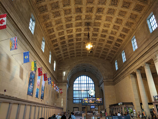
Figure 2.16. Guastavino Vault, Union Station, Toronto (Architects: Ross & Macdonald, John Lyle, 1914–1920; Photograph: Shane Laptiste).
One of the most beautiful examples of Guastavino vaulting—the Oyster Bar in Grand Central Station in New York City—is shown in the following video:
Ochsendorf, J. [National Building Museum]. (2013, December 11). Palaces for the people: The Oyster Bar in Grand Central Terminal, New York, NY. [Video file].
Required Reading
- Chapter 5: Designing a Building on a Vertical Site in Form and Forces: Designing Efficient, Expressive Structures
- Chapter 8: Designing Unreinforced Masonry in Form and Forces: Designing Efficient, Expressive Structures
Focus Questions
You do not need to submit final written answers for these questions, but you should be able to answer them to your own satisfaction and add resources to your Personal Archive that support your answers.
- Identify different types of connectors in buildings and other structures near where you live. Take pictures of a roller or rocker joint, a pin or hinge joint, and a fixed joint and add them to your personal archive.
- Could you use any of the structures you will create in Project 2 in any of your design projects?
Discussion Forum Question
In general, do you think the form of contemporary buildings acknowledges or ignores the structural forces that act on them? Submit your response here.
Evaluation
Your work will be evaluated using the marking matrix outlined in the Evaluation and Grading section of the Course Orientation.
Project Description
Graphic Statics, Suspended Structures, and Catenaries
In this series of projects, you will continue designing structures through graphic statics. Your work here will consist of four small projects:
- Drawing a beam and finding reactions
- Calculating the reactions in beams (from Chapter 5)
- Completing the design of a brick vault for a house using Worksheet 08A
- Exploring catenary structures in your own work
Each of these is described in more detail below, but to complete any of them, you will first need to read the required readings for this section carefully.
Project 2a: Drawing a Beam and Finding Reactions
Draw by hand the beam with a single concentrated load described in Chapter 5 of your eText (Figure 5.17). Follow the steps on page 124 that explain how to find beam and truss reactions. Now draw a new beam, supported near its ends 25 ft apart, with a single load of 425 lb, at a distance of 5 ft from its left support. Resolve the reactions of this new beam. Take a photo or scan your drawing and solution to include in your Collection submission.
Optional: Go to the drawings page on the eQUILIBRIUM website. Using the interactive drawing Internal forces in a beam – point load, try to replicate the beam with a single concentrated load described in Chapter 5 of your eText (Figure 5.17). The forces and lengths may differ with the numbers provided in the eText, but the resulting diagrams would be similar. This may be used as a substitute for the hand-drawn diagrams requested above. (Note: You may also be interested to test the reactions in the other Internal forces in a beam drawings shown on the website; e.g., line load, superposition, and cantilever with point load.)
Project 2b: Calculating Reactions in Beams
Complete Question 2 at the end of Chapter 5 in Form and Forces: Designing Efficient, Expressive Structures. (Note: Due to missing information in diagram 5.31 (d), you are only required to answer questions for diagrams 5.31 (a), (b), and (c).)
Project 2c: Brick Vault
Use the methods outlined in Chapter 8 and Worksheet 08A to develop the design of a roof for a house using brick vaulting.
Project 2d: Applying What You Have Learned
In designing the vaulting for Sagrada Familia, Antoni Gaudi used a technique that mimicked the way you designed your structures for Projects 1b and 1c—but he did it upside down. In a scale model of the cathedral (shown below and now displayed in the building’s crypt), he hung wires from a board and added weights to them. These curves (when turned over) are also the most effective shape for vaults. The wires are totally in tension and the vaults are totally in compression.

Figure 2.17. Gaudi’s hanging and weighted structural model for Sagrada Familia.
For this project, you will make something similar. You will need a ball of string, a dozen beads, and a piece of cardboard. This is harder than it looks, so you will need to spend some time doing it. Thin, strong string works best for this.
On the cardboard, draw the outline of the floor plan of your project you identified earlier. (For this project, you can also use another building you designed in one of your studios or a building you are working on at work. If neither situation applies, then draw a simple shape like the one shown in Figure 2.18.)
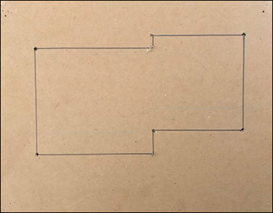
Figure 2.18. Draw a rough plan on a piece of cardboard and punch holes where you want to create the vaults.
Punch holes into the cardboard at key points in the plan (e.g., the corners). Thread the string through one hole, slide a bead onto it, and then thread it through another hole. Add additional beads for weights. Looping the string once through each bead keeps it in place but still allows you to slide the bead along the string (as shown below).
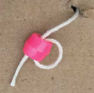
Figure 2.19. Loop the string once through each bead. This holds it in place but allows you to still change its position.
Tape or use beads to secure the ends of the string on the back of the cardboard. You’ll probably want to adjust the lengths, so looping the string through the beads (as shown below) works here as well.
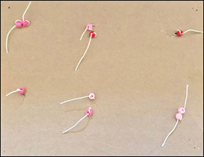
Figure 2.20. Backside of cardboard with strings secured with looped beads.
Repeat with another length of string and more beads. You can try threading two or more pieces of string through the same bead.
Turn your work upside down so the strings hang down. Adjust the lengths of the strings and the beads until you have a shape you like. You can add additional weights using clips (as shown in Figure 2.21). Take a picture of it; then rotate the picture upside down and you will have the shape of a roof.
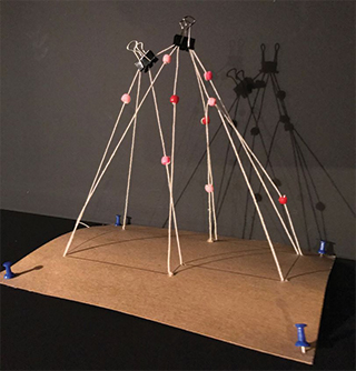
Figure 2.21. When turned upside down, the hanging structure provides the basis for a vaulted one.
You can also hang a piece of cloth from your outline to get a similar shape.
Note: There are additional references to this work in Chapter 8 of Form and Forces: Designing Efficient, Expressive Structures.
Review Terms
You should be familiar with and able to define the following terms and concepts:
concurrent coplanar force systems
eccentric loads
equivalent force systems
fixed connector
force systems
free vector
moment of a couple
moment of a force
nonconcurrent force systems
parallel coplanar force systems
pin connector
rocker connector
roller connector
trigonometric functions
Submission Requirements
For Collection 1, include the following items from Project 2:
- Project 2a – one image of a beam and its reactions
- Project 2b – answers to Question 2 at the end of Chapter 5 in Form and Forces (Note: Due to missing information in diagram 5.31 (d), you are only required to answer questions for diagrams 5.31 (a), (b), and (c). Remember to show your work.)
- Project 2c – Worksheet 08A
- Project 2d – three images of your catenary structure
Note: Now that you have completed Projects 1 and 2, save them together as Collection 1 and submit the PDF to your academic expert for assessment. Scan your study images and materials and add them to your Personal Archive.
Footnote
[2] From “Equivalent Force Couple System,” by J. Moore, Adaptive Map Digital Textbook Project (CC-BY-3.0)